Design for Disassembly
As part of the development of a new CE-Based Design Methodology for Affordable Housing,
Design for Disassembly Construction Detailing:
- Provide comparative drawings of traditional vs. DfD details for biobased (including timber-frame), steel, and concrete structures.
- Offer practical guidance for architects and contractors to design buildings that can be easily dismantled, avoiding demolition and reducing waste.
Light Wood Frame
Exterior Wall Comparison
Residence type: Low-rise 2-storey housing designed for Montreal, Quebec
Structure: Light wood frame
Reclaimable materials: Wood lumber, wood-fibre insulation, wood cladding, plywood panels, cork tiles.
Roof – Vertical View
Traditional Construction

- 3 mm EPDM membrane, fully adhered
12.7 mm cover board
140 mm min. rigid foam insulation
WRB membrane
19 mm plywood roof deck
241 mm roof cavity with 38x241mm
timber joists, filled with fiberglass batt insulation
13mm gypsum ceiling board, screwed/taped/mudded - Parapet steel coping with drip edge. Continuous coping cleat
Bevelled lumber plates
Flashing membrane
Parapet rigid insulation - Steel counter-flashing
Termination bar set in sealant
Fully adhered TPO water control
membrane
12.7mm plywood/OSB sheathing
38x89mm “rough” parapet top plates
89mm fiberglass batt insulation
DESIGN FOR DISASSEMBLY (DfD)

- 3 mm EPDM membrane, mechanically fastened
12.7 mm cover board
140 mm min. TimberBoard rigid WFI, R-19 min.
WRB membrane
19 mm plywood roof deck, screw-fixed to joists
241 mm roof cavity with 38x241mm timber joists, filled with TimberBatt wood-fibre insulation, R26.8 min.
Smart vapour retarder
19 mm interior service cavity with 19x64mm battens
3 mm cork ceiling tiles glued to 12.7 mm plywood panels, screw-fixed to battens
Nominal Roof R-Value: R-48.9 min - Removable parapet steel coping with drip edge
Screwed continuous coping cleat
Bevelled lumber plates
Flashing membrane
Parapet rigid WFI - Steel counter-flashing
Termination bar set in sealant
Non-adhesive water control membrane
12.7mm plywood/OSB sheathing
38x89mm “rough” parapet top plates
89mm WFI batt insulation - Cant strip
- Long roof screw with 50mm stress plate fixing cover board/WFI
Interstorey Floor and Window – Vertical View
Traditional Construction

- 9.5 mm engineered wood floor
2 mm underlayment
19 mm plywood/OSB subfloor
241 mm floor cavity with 38x241mm
timber joists, with fiberglass batt at rim
13 mm gypsum ceiling board, screwed to joists, taped and mudded - Flanged window nailed through flange into strapping
- Sloped metal sill pan
- Weep hole
- Sill insulated with spray foam
- Backer rod and sealant at perimeter gap
- Metal flashing
- Adhered sealing tape lapped into WRB
DESIGN FOR DISASSEMBLY (DfD)

- 9.5 mm engineered wood click-lock planks
2 mm underlayment
19 mm plywood/OSB subfloor screwed to joists
241 mm floor cavity with 38x241mm timber joists, with TimberBatt at rim
19 mm interior service cavity with 19x64mm battens
13 mm cork ceiling tiles glued to plywood/OSB panels, screw-fixed to battens - Rim joist
- Joist hanger
- Non-flanged window, screw-fixed with metal Z-clips
- Finish sill, screwed to blocking
- Metal flashing
- Taped air seal; flashing lapped into WRB
- Under-sill WFI
- Vapour-permeable sealing tape under sill
- Sloped metal sill pan
- Weep hole
Wall, Ground Floor, Foundation – Vertical View
Traditional Construction

- 19 mm vertical wood cladding, face-nailed to strapping
19×64 mm horizontal timber battens
19×64 mm vertical timber battens, forming rainscreen cavity
89 mm XPS rigid exterior insulation
Self-adhered WRB membrane stapled to sheathing
19 mm plywood/OSB sheathing
38x89mm timber studs with 89 mm fibreglass batt
Polyethylene vapour barrier
13mm gypsum board, screwed to studs, taped, mudded, & painted - M12 anchor bolt with washer fixes 38×89 mm pressure-treated sill plate to foundation over 5 mm EPDM sill gasket
- Insect screen
- Base flashing
- 9.5 mm engineered wood floor
2 mm underlayment
5 mm self-levelling concrete topping
152 mm concrete slab-on-grade
15 mm vapour/radon retarder
152 mm granular base
DESIGN FOR DISASSEMBLY (DfD)

- 19 mm Shou Sugi Ban vertical wood cladding, demountable
38 mm rail system rainscreen cavity
89 mm TimberBoard rigid wood-fibre insulation, R-12
WRB membrane, taped at seams
19 mm plywood/OSB sheathing
38x89mm timber studs with 89 mm
TimberBatt wood-fibre batt, R-14
Smart vapour retarder, taped at seams
3 mm cork finish tiles glued to 12.7 mm plywood/OSB backing panels, demountably hung with wooden cleat
Nominal Wall R-Value: R-29.5 - Long structural screws fix rail through WFI
into studs - Monarch MFEXT-1250 & MFPROJ-375 or similar;
screw-fastened metal rails & Z-clips
create rainscreen cavity - Wood cleats for demountably hanging finish panels
- M12 anchor bolt with washer fixes 38 x 89 mm pressure-treated sill plate to foundation over 5 mm EPDM sill gasket
- Insect screen
- Base flashing
- 9.5 mm engineered wood click-lock planks
2 mm underlayment
5 mm self-levelling concrete topping
152 mm concrete slab-on-grade
15 mm vapon/radon retarder
152 mm granular base
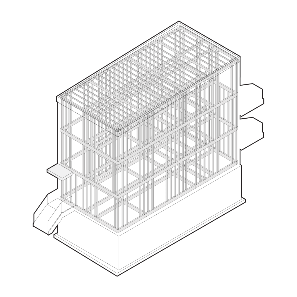
exploded axonometric diagram – Vertical View

The light wood frame DfD assembly adapts conventional light wood framing into a more accessible, repairable, and material-recoverable system. The primary structure remains familiar: 38 × 89 mm studs, joists, rim boards, sill plates, and plywood or OSB sheathing. The major difference is that the surrounding layers are organized for disassembly rather than permanent adherence. In conventional light wood frame construction, the envelope often depends on face-nailed cladding, stapled or self-adhered water-resistant resistive barrier (WRB), fiberglass batts, polyethylene vapour barrier, spray foam at openings, and gypsum board finishes. These layers perform well initially but are difficult to separate cleanly during renovation or demolition [1].
This light wood frame strategy is closely informed by the project’s RECAST demonstration. The demonstration communicates DfD principles through a built prototype, including removable layers, visible fasteners, and secondary material integration. The assembly proposed here refines the demonstration into a more systemic design strategy. It preserves the practical lessons of prototyping while adjusting details to address envelope continuity, construction feasibility, and long-term disassembly.
In the DfD version, the exterior wall is organized as a sequence of removable layers. The outer finish is vertical Shou Sugi Ban cladding, a traditional Japanese wood preservation technique in which the surface of timber is charred to create a protective carbon layer. The method can improve resistance to weathering, insects, and surface decay while producing a dark, durable aesthetic; it is also useful here because second-life wood cladding can be preserved without conventional stains or coatings [6]. The cladding is panelized and demountably hung from a screw-fastened rail and Z-clip system, using Monarch MFEXT-1250 and MFPROJ-375 or similar rails. These rails create the rainscreen cavity and are mechanically fastened through the wood-fibre insulation and sheathing into the timber studs. This allows the cladding to be removed first, followed by the rails, insulation, WRB, and sheathing if needed [7].
The insulation strategy replaces conventional fiberglass and foam with TimberHP TimberBoard rigid wood-fibre insulation outside the sheathing and TimberHP TimberBatt within the stud cavity. The exterior TimberBoard improves continuity and reduces thermal bridging, while the interior batt maintains a low-carbon, biobased cavity insulation strategy. TimberHP describes TimberBoard as a rigid, vapour-open wood fibre board suitable for continuous exterior insulation in wall, roof, and floor applications, and TimberBatt as a flexible wood-fibre batt insulation for thermal, acoustic, and vapour-open assemblies [8]. The WRB is taped at seams rather than fully adhered, reducing destructive removal. The smart vapour retarder is placed on the interior side of the stud cavity and detailed with gaskets or acoustic caulking at specific penetration points. Horizontal wood cleats are installed at regular intervals, creating a service zone for wiring and allowing conduits or brackets to be added without repeatedly puncturing the vapour retarder [9].
Interior finishes replace gypsum board with demountable plywood panels adhered to cork tiles. Cork tiles are glued to 12.7 mm second-life plywood backing panels, which are hung on wood cleats gasketed or caulked through the vapour retarder rather than taped and mudded. This allows the interior finish layer to be removed as panels instead of being demolished as gypsum waste. Fire performance must be treated cautiously: cork and plywood finish panels should not be assumed to perform like fire-rated gypsum assemblies without testing. Where required, a post-applied fire-retardant treatment such as Flame Stop II can be considered. Flame Stop II is listed as a Class A treatment on Douglas fir, although final fire performance for cork and plywood assemblies would need project-specific confirmation [10].
Openings are also treated as removable components. Instead of a conventional flanged window nailed through sheathing and sealed with spray foam, the DfD assembly uses a non-flanged window screw-fixed with metal Z-clips into a wood buck. Flashing tape is lapped into the WRB, wood-fibre insulation is placed under the sill, and vapour-permeable sealing tape is used at the sill condition. This creates a deep reveal and allows the window to be removed without destroying adjacent layers (See Interstorey Floor and Window). In conjunction, shadow gaps in the vertical wood cladding at the window create weep holes for rainscreen drainage while also providing a subtle aesthetic. At the base, an M12 anchor bolt with washer fixes the 38 × 89 mm pressure-treated sill plate to the concrete foundation over a 5 mm EPDM sill gasket, creating a dry capillary break and a legible foundation connection (Wall, Ground Floor, Foundation) [11].
The roof follows the same logic. Instead of fully adhered layers, the EPDM/TPO membrane is mechanically fastened or loose-laid where possible. A long roof screw with a 50 mm stress plate fixes the cover board and wood-fibre insulation to the roof deck. A removable steel coping with drip edge is screwed to a continuous coping cleat at the parapet (Roof). In disassembly, the sequence begins with coping and roof membrane, then roof cover board and insulation, then exterior cladding and rails, then window units, then interior finish panels, and finally the timber structure and sill anchorage [12].
References
Mass Timber
Exterior Wall Comparison
Residence type: Low-rise 2-storey housing designed for Montreal, Quebec
Structure: Mass Timber
Reclaimable materials: DLT panels, wood-fibre insulation, wood cladding, plywood panels.
Roof – Vertical View
Traditional Construction

- 3 mm EPDM membrane, fully adhered
12.7 mm cover board
235 mm min. rigid polyisocyanurate insulation
Air/vapour-control membrane
12.7 mm plywood/OSB roof diaphragm deck
231 mm CLT roof panel
13 mm gypsum ceiling - Parapet steel coping with drip edge
Continuous coping cleat
Bevelled lumber plates
Flashing membrane
Parapet rigid insulation - Steel counter-flashing
Termination bar set in sealant
Fully adhered TPO water control membrane
12.7mm plywood/OSB sheathing
38x89mm “rough” parapet top plates
89mm fiberglass batt insulation
Cant strip - Partially-threadead screws connect CLT roof panel bearing on wall panel
DESIGN FOR DISASSEMBLY (DfD)

- 3 mm EPDM membrane, mechanically fastened
12.7 mm cover board
235 mm min. TimberBoard rigid WFI, R-34 min.
Smart air/vapour-control membrane
12.7 mm plywood/OSB roof diaphragm deck
231 mm DowelLam DLT roof panel, R-11.37 (exposed DLT ceiling)
Nominal Roof R-Value: R-46.5 min. - Removable parapet steel coping with drip edge
Screwed continuous coping cleat
Bevelled lumber plates
Flashing membrane
Parapet rigid WFI - Steel counter-flashing
Termination bar set in sealant
Non-adhesive water control membrane
12.7mm plywood/OSB sheathing
38x89mm “rough” parapet top plates
89mm WFI batt insulation - Cant strip
- Long roof screw with 50mm stress plate fixing cover board/WFI
- Roof to wall panels connected by bracket fixed with timber screws
Interstorey Floor and Window – Vertical View
Traditional Construction

- 9.5 mm engineered wood planks
2 mm underlayment
12.7 mm plywood/OSB subfloor
180 mm CLT floor panel
13 mm gypsum ceiling - Partially-threaded screws connect
DLT floor bearing on DLT wall panel below - Flanged window nailed through flange into strapping
- Sloped metal sill pan
- Weep Hole
- Sill insulated with spray foam
- Backer rod and sealant at perimeter gap
- Metal flashing
- Adhered sealing tape lapped into WRB
DESIGN FOR DISASSEMBLY (DfD)

- 9.5 mm engineered wood click-lock planks
2 mm underlayment
12.7 mm plywood/OSB diaphragm subfloor
180 mm DowelLam DLT floor panel (exposed DLT ceiling) - Diaphragm subfloor screw-fixed to DLT floor panel
- DLT floor panel bears on DLT wall below
Partially-threaded wood screws connect panels - Non-flanged window, screw-fixed with metal Z-clips
- Taped air seal flashing lapped into WRB
- Under-sill WFI
- Finish sill, screwed to blocking
- Metal flashing
- Vapour-permeable sealing tape under sill
- Sloped metal sill pan
- Weep hole
Wall, Ground floor, Foundation – Vertical View
Traditional Construction

- 19 mm vertical wood cladding, nailed to strapping
19×64 mm horizontal timber battens
19x64mm vertical battens, forming rainscreen cavity
WRB membrane, taped at seams
140 mm rigid XPS insulation
Vapour barrier
147 mm CLT wall panel
13 mm gypsum board finish - CLT panel bears on concrete with pressure-treated sill plate, connected with cast-in anchor bolts
- Insect screen
- Base flashing
- 9.5 mm engineered wood click-lock planks
2 mm underlayment
5 mm self-levelling concrete topping
152 mm concrete slab-on-grade
15 mm vapour barrier
152 mm granular base
DESIGN FOR DISASSEMBLY (DfD)

- 19 mm Shou Sugi Ban vertical wood cladding
38 mm rainscreen cavity supported by rail system
WRB membrane, taped at seams
140 mm TimberBoard rigid wood-fibre insulation, R-19
Smart vapour retarder, taped at seams
12.7 mm plywood/OSB shear sheathing
136 mm DowelLam DLT wall panel, R-6.7
Nominal Wall R-Value: R-27.3 - Monarch MFEXT-1250 & MFPROJ-375 or similar
screw-fastened metal rails & Z-clips demountably support cladding & create rainscreen cavity - Insect screen
- Base flashing
- Exposed DLT interior finish
- DLT panel bears on continuous steel shoe, fastened with M16 anchor bolt
- 9.5 mm engineered wood click-lock planks
2 mm underlayment
5 mm self-levelling concrete topping
152 mm concrete slab-on-grade
15 mm vapour/radon retarder
152 mm granular base
exploded axonometric diagram – Vertical View

The mass timber DfD assembly uses dowel-laminated timber (DLT) panels rather than cross-laminated-timber (CLT) to apply mechanically laminated construction and avoid structural adhesive between panel laminations.. Conventional CLT relies on adhesive-bonded cross-laminated layers, which limits future separation into individual laminations. DLT insteaduses hardwood dowels to friction-fit boards together. DowelLam’s current design guide describes DLT panels asfree of metal fasteners and adhesive between laminations, while noting that longer panels may contain trace adhesive where finger-jointed boards are used [1]. DowelLam also reports that DLT floor assemblies have achieved a two-hour fire resistance rating with a 5.5-inch panel tested to ASTM E119 / CAN/ULC-S101and that assemblies incorporating an acoustic isolation mat and concrete topping can achieve STC and IIC values above 50 ; ; final fire and acoustic performance must nevertheless be verified for the exact project assembly [2]. The corresponding roof, floor/window, foundation, and exploded axonometric DfD details are shown in the above figures.
The wall assembly begins with the same demountable exterior strategy as the light wood frame system: vertical Shou Sugi Ban cladding, a screw-fastened metal rail and Z-clip rainscreen system, continuous TimberBoard wood-fibre insulation, a taped WRB, and plywood or OSB shear sheathing. The structural layer is a 136 mm DowelLam DLT wall panel, with its room-side face left exposed as the primary interior finish. This avoids an additional gypsum finish, preserves direct access to the structural panel for insepection and future recovery, and takes advantage of the warmth and visual quality of mass timber (see Figures 3.23 and 3.24). Over time, the exposed DLT is expected to develop a patina. Screw holes from art, shelving, or everyday use can be filled with wood filler or timber dowels; alternatively, demountable hanging rails can be installed, similar to gallery systems, so that future wall use does not damage the structural surface [3].
Because the DLT panel is exposed on the interior, the air- and vapour-control layers are located outward of the structural panel rather than behind a separate finish. In the proposed wall buildup, the smart vapour-control membrane is positioned outboard of the plywood sheathing and DLT structure and inboard of the exterior wood-fibre insulation, while the vapour-open WRB remains on the exterior side of the wood-fibre insulation. exterior to This maintains the exposed interior timberwhile coordinating drying potential and control-layer continuity (Tabs Wall, Ground Floor, Foundation; and Exploded Axonometric Diagram) [4].
The mass timber floor and roof panels are also designed as salvageable components. DLT floor and roof panels span one-way across the 16 ft building width and repeat as modular panels along the 40 ft building length. DowelLam notes that DLT is a one-way spanning system and that diaphragm action may be achieved through strategies such as concrete topping or shop-installed sheathing [5]. In this proposal, the floor panel-to-panel joint is detailed as a simple butt joint between adjacent DLT panels, reinforced by a screw-fixed plywood or OSB diaphragm layer bridging across the joint. This layer provides diaphragm continuity while remaining mechanically removable. Wall panel-to-wall panel joints are similarly dry: adjacent storey-height wall panels are aligned at a vertical joint and connected with a screw-fixed plywood or timber spline that overlaps both panels (Tabs Interstorey Floor and Window and Exploded Axonometric Diagram). This avoids adhesives and allows panels to be separated after fasteners are removed [6].
At interstorey floors, partially threaded timber screws connect DLT floor panels to DLT wall panels. At the roof, a bracket fixed with timber screws connects roof and wall panels, maintaining a modular and visible connection (Tabs Roof and Interstorey Floor and Window). This contrasts with conventional mass timber construction, where CLT roof or floor panels often bear on walls and are connected with concealed self-tapping screws that are efficient but not necessarily organized for repeated disassembly [7].
The modular foundation connection is the key DfD adaptation. Instead of a conventional CLT wall bearing on a pressure-treated sill plate connected with cast-in anchors, the DLT wall bears on a continuous steel shoe (Tab Wall, Ground Floor, Foundation). The shoe is bolted to the concrete foundation with anchor bolts, with an EPDM or neoprene pad below for capillary separation and tolerance. At end of life, the DLT panel can be disconnected from the slab by removing the bolts and lifting the panel from the shoe. The overall disassembly sequence is therefore: roof membrane and coping, roof insulation, cladding panels and rail system, windows, panel-to-panel splines/straps, roof and floor screws, diaphragm layers, DLT panels, steel shoe, and finally the concrete foundation [8].
References
Precast Concrete
Exterior Wall Comparison
Residence type: Low-rise 2-storey housing designed for Montreal, Quebec
Structure: Precast concrete
Reclaimable materials: Single-wythe precast concrete wall panels, precast hollow core floor & roof planks, wood-fibre insulation, wood cladding.
Roof – Vertical View
Traditional Construction

- 3 mm EPDM membrane, fully adhered
12. 7 mm cover board
R-41 rigid foam roof insulation
200 mm hollowcore roof plank
10 mm bearing pad at wall support - Parapet steel coping with drip edge
Continuous coping cleat
Bevelled lumber plates
Flashing membrane
Parapet rigid insulation - Steel counter-flashing
Termination bar set in sealant
Fully adhered TPO water control membrane
Cant strip - HC roof plank bears on precast wall ledge over neoprene bearing pad;
Bent bar, grouted keyway, cast-in dowel joints for roof-wall tie
DESIGN FOR DISASSEMBLY (DfD)

- 3 mm EPDM membrane, mechanically fastened
12.7 mm cover board
51 mm min. TimberBoard rigid WFI (top layer), R-7 min.
235 mm rigid WFI (base layer), R-34
Smart air/vapour-control membrane
200 mm precast hollowcore roof plank
Nominal Roof R-Value: R-42.1 min. - Long screw with 50 mm stress plate fixing cover board/WFI
- Removable parapet steel coping with drip edge
Screwed continuous coping cleat
Bevelled lumber plates
Flashing membrane
Parapet rigid WFI - Steel counter-flashing
Termination bar set in sealant
Non-adhesive water control membrane - Cant strip
- Bolted L-angle restraint provides roof-to-wall tie/upift restraint; hollowcore roof plank bears on precast wall ledge over neoprene pad
Interstorey Floor and Window – Vertical View
Traditional Construction

- 9.5 mm engineered wood floor
2 mm underlayment
200 mm precast hollowcore plank - HC plank bears on ledge in precast wall over 10 mm neoprene bearing pad
Conventional grouted keyway, bent bar & cast-in dowel joints
Grouted/wet joints limit disassembly - Flanged window nailed through flange into concrete
- Sloped metal sill pan
- Weep hole
- Sill insulated with spray foam
- Backer rod & sealant at perimeter gap
- Metal flashing
- Adhered sealing tape
DESIGN FOR DISASSEMBLY (DfD)

- 9.5 mm engineered wood click-lock planks
2 mm underlayment
200 mm precast hollowcore plank
Concrete ledge formed in precast wall panel
Precast wall panel below - HC plank bears on concrete ledge over
10 mm neoprene bearing pad
Bolted L-angle provides lateral tie - Non-flanged window, screw-fixed with metal Z-clips
- Taped air seal flashing lapped into WRB
- Under-sill WFI
- Finish sill, screwed to blocking
- Metal flashing
- Vapour-permeable sealing tape under sill
- Sloped metal sill pan
- Weep hole
Wall, Ground floor, Foundation – Vertical View
Traditional Construction

- 75 mm exterior precast concrete wythe
150 mm rigid foam insulation
150 mm interior structural precast concrete wythe (exposed concrete interior) - Exterior wythe as durable weather face; difficult material separation.
No separate
WRB/VB; backer rod & sealant at panel joints provide water/air control - Precast wall set on shims
Base joint filled with nonshrink grout; reinforced with rebar - Base flashing
- 9.5 mm engineered wood floor
2 mm underlayment
5 mm self-levelling concrete topping
152 mm concrete slab-on-grade
15 mm vapour barrier
152 mm granular base
DESIGN FOR DISASSEMBLY (DfD)

- 19 mm Shou Sugi Ban vertical wood cladding
38 mm rainscreen cavity supported by KWS
MFI clips & D-Rail
WRB membrane, taped at seams
184 mm TimberBoard rigid WFI, R-26
Smart vapour retarder
150 mm precast single-wythe concrete wall panel (exposed concrete finish)
Nominal Wall R-Value: R-27.4 - Knight Wall Systems D-Rail continuous rail & MFI clips anchor cladding + WFI to concrete
- Peikko SUMO 20-H wall shoe cast into concrete panel base
HPM anchor bolts into foundation in shoe
Neoprene levelling shims below wall - Insect screen
- Base flashing
- 9.5 mm engineered wood click-lock planks
2 mm underlayment
Self-levelling concrete topping
152 mm concrete slab-on-grade
15 mm vapour/radon retarder
152 mm granular base
exploded axonometric diagram – Vertical View
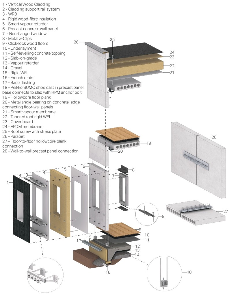
The precast concrete DfD assembly shows how a high-mass, conventionally linear material system can be reorganized for circular reuse. Precast construction already has advantages for speed, quality control, fire performance, sound separation, and prefabrication. The Canadian Precast Concrete Institute (CPCI) identifies its Design Manual as a Canadian reference for the design, manufacture, and installation of precast reinforced and prestressed concrete. The CPCI also identifies hollow core slabs as common solutions for floor and roof construction [1]. However, conventional precast buildings often rely on grouted joints, cast-in dowels, welded or grouted keyways, bent bars, and composite sandwich panels that embed insulation between concrete wythes. These systems are efficient to erect but difficult to separate at end of life. Research on concrete DfD argues that concrete buildings should be designed to shift from a linear demolition model toward a cyclic model based on disassembly, reuse, and adaptation [2]. The proposed roof, floor/window, foundation, and overall exploded DfD assembly are shown in the above figures.
The DfD version uses a single-wythe 150 mm precast concrete panel rather than a double-wythe insulated sandwich panel. In a conventional sandwich panel, insulation is embedded between concrete wythes and connected through the panel, which limits later material separation. In the DfD wall, the insulation is instead treated as a separate accessible exterior layer. A 184 mm layer of TimberBoard wood-fibre insulation is placed outside the precast panel, behind a Knight Wall Systems MFI-type bracket and continuous D-Rail rainscreen system. The mechanically fastened rail-and-bracket system carries the rainscreen cladding back to the concrete substrate while maintaining a separate rainscreen support layer that can be removed independently (Tabs Wall, Ground Floor, Foundation; and Exploded Axonometric Diagram) [3].
The interior face of the precast panel is left exposed. This reduces material use, avoids gypsum board, and gives the concrete wall its own architectural character. The exposed finish also reinforces the contrast between systems: light wood frame uses demountable cork-on-plywood panels, mass timber uses exposed DLT, and concrete uses exposed precast concrete. The window strategy remains consistent with the other assemblies: non-flanged windows are screw-fixed with metal Z-clips, flashed into the WRB membrane, and sealed without relying on destructive spray foam [4]. The exposed-wall strategy is visible in Tabs Wall, Ground Floor, Foundation; and Exploded Axonometric Diagram, while the removable window condition is detailed in Tab Interstorey Floor and Window.
The base connection adapts the Peikko SUMO 20 wall shoe connected to HPM anchor bolts as a mechanically accessible connection at the panel base (Figure 3.27). In standard Peikko SUMO installation, the wall is positioned on shims, the nuts and washers are tightened, and the joint beneath the wall and the bolt recesses are subsequently grouted; once the grout has reached sufficient strength, the connection is finalized [5]. The DfD proposal proposes using only the dry bolted connection so that fasteners inside the shoe pocket remain accessible and the panel can be unbolted for future reuse; this is treated as a conceptual reversible adaptation, requiring project-specific structural and manufacturer review.
Floors and roofs use 200 mm precast hollow core planks rather than solid concrete slabs. Hollow core reduces material use and supports prefabricated, modular installation. CPCI describes hollow core slabs as prestressed precast floor units whose internal voids reduce slab weight by approximately 50 percent, with common depths including 200 mm and widths around 1,220 mm. 26 In the DfD interstorey condition, hollow core planks bear on a precast wall ledge over a 10 mm neoprene bearing pad. Vertical gravity load is carried by bearing, while a bolted L-angle provides lateral tie or uplift restraint rather than acting as the primary support. At the roof, the same logic applies: the hollow core roof plank bears on a precast ledge over neoprene, with bolted steel angle restraint for roof-to-wall tie (Tabs Roof and Interstorey Floor and Window). This differs from traditional construction, where solid concrete roof or floor slabs may bear on ledges over neoprene but are tied with bent bars, grouted keyways, or cast-in dowel joints. [6]
Panel-to-panel connections are also made legible and removable. Storey-height precast wall panels are connected with a recessed bolted steel splice plate, fixed with bolts into cast-in threaded inserts (Tab Exploded Axonometric Diagram). Adjacent hollow core planks are shown with a replaceable gasket or sealant joint and, where diaphragm continuity is required, a removable flat steel tie plate bolted with bolts into cast-in inserts coordinated with the hollow core manufacturer. This approach aligns with concrete DfD research and with built precedents such as Circle House, where precast concrete elements were designed for future dismantling using mechanical joints, steel plates, bolts, screws, and other removable connection strategies [7].
The disassembly sequence begins with the roof coping, mechanically fastened roof membrane, stress plates, cover board, and wood-fibre roof insulation. The cladding panels and D-rail system are then removed, followed by the exterior wood-fibre insulation and WRB membrane. Windows are unscrewed from their Z-clips. Hollow core planks are disconnected by removing bolted restraints and tie plates, then lifted from bearing pads. Wall panels are unbolted at splice plates and Peikko shoe pockets, allowing the precast elements to be recovered as large structural components rather than crushed as demolition waste (Tab Exploded Axonomtric Diagram). [8]